
This interesting case study depicts an R&D; team that collaborated with a
university to develop a new industrial sensor based on Giant Magnetoresistance
(GMR) technology, illustrating how magnetics selection and signal processing design
combined to solve a difficult sensing requirement.
Regardless of the markets they serve, embedded component manufacturers are competing in a never-ending race to improve existing products and introduce new products. New products are usually the result of careful market analysis and consideration of feedback from current sales efforts. There is always a need to balance the historical legacy of existing product lines with the advancing capability of new technology. As the old saying goes, ìdonít throw the baby out with the bath water.î In the world of industrial sensors, legacy constraints include form factor, interface, electrical requirements, and backwards compatibility.
One real-world example from the world of die casting, an $8 billion per year business that supplies the world with cast metal parts, demonstrates the development of a new embedded industrial sensor based on a legacy product. These parts are often used in the automotive industry; however, die casting is a common method for manufacturing all types of aluminum, magnesium, and zinc parts.
The die casting process involves forcing molten metal into a two-piece die (or mold) using a hydraulic ram. In a typical system, the molten metal is transferred into the system using a ladle that pours the material into a sleeve. The metal is then quickly and forcibly pressed into the die by the hydraulic ram, where it hardens. Subsequently, the die is opened and the part is removed for further processing. Throughout this process, precisely controlling the hydraulic ramís motion is essential to ensure high-quality castings, efficient cycle times, and extended die life.
The process parameters for controlling the hydraulic ram include velocity (during the phase when the molten metal is being moved through the sleeve up to the die) and position (during the squeeze phase, when the metal has entered the die and quickly begins hardening). Controlling the latter phase is particularly important to ensure casting quality; the die must be completely filled before appreciable hardening of the metal occurs. Typical velocities used range from 100-400 inches per second. Accurate control requires robust linear position and velocity-sensing capability.
Comparing position-sensing technologies
In general, linear position sensing is a broadly applicable technology in the industrial setting. Hundreds of vendors offer solutions based on a dozen or so core technologies, including potentiometers, magnetoresistance, capacitance, encoders, Hall Effect, LVDT, and inductive.
In extreme environments, some of these technologies are not suitable for linear position sensing: Potentiometers are not generally appropriate for high-speed sensing because of mechanical coupling and wear, and capacitive sensors have a narrow range of travel and narrow operating temperature range, as do optical devices. For controlling rugged machinery such as die casting equipment, a common approach is Hall Effect, in which an electrical potential is detected across an axis perpendicular to an applied current flow and a magnetic field. Magnetoresistance, where the presence or absence of a magnetic field affects the sensorís electrical resistance, is also used. Both approaches allow the magnet and sensor to be encapsulated, thereby reducing the possibility of damage from extreme environmental sources. They also share the benefit of being noncontact, so that speeds and sensitivity are not limited by mechanical coupling.
In this die casting example, the Visi-Trak Sensors development team had extensive experience and success with a design based on a Hall Effect sensor. This design formed the basis for a product that sensed the velocity of a moving rod traveling near the sensor. The rod, which is a companion product, is a steel shaft with grooves evenly spaced along its length. The grooves are over-plated with chrome and machined to an even surface. The result is a smooth, polished rod that presents a regularly varying magnetic response. This rod can be used as the piston rod in a hydraulic or pneumatic cylinder or mounted as a follower on other moving equipment. The rod, coupled with the Hall Effect sensor, enables accurate velocity measurement.
As often happens, production pressures and customer requests spurred the developers to look for other approaches. First of all, the manufacturer of the Hall Effect component discontinued the part the developers had relied on for a number of years. This necessitated changes in the circuit board and design. Also, the project demanded a sensor product that supported position sensing (rather that velocity) with high resolution (better than .001"). Developers also wanted to support higher velocity capability (up to 200" per second, using the typical 20 grooves per inch rod). Finally, they wanted to increase the sensorís sensitivity so that it could be situated farther away from the moving rod. This would reduce the opportunity for accidental damage from bent rods or improper installation.
Developers knew the goals would be difficult to achieve and that they didnít possess all the necessary tools (either hardware or software) to meet those goals. The following discussion provides an overview of the approach the team used to tackle this problem.
Sensing modality selection and implementation
The first step in developing the new sensor was to evaluate all the possible sensing modalities. Developers created a matrix that allowed them to objectively compare each feature: contact/noncontact, resolution, vibration stability, temperature stability, linearity, hysteresis, velocity, and more. They also had to consider compatibility with the existing sensor form factor and interface specification. It became apparent that GMR was a suitable sensing technique. GMR is a form of magnetorestriction with great sensitivity, resolution, and linearity. Additionally, chip-based GMR sensors are readily available and packaged similarly to Hall Effect sensors.
GMR is a type of quantum mechanical effect discovered in 1988 by Peter Gr¸nberg of the J¸lich Research Center (Germany) and Albert Fert of the University of Paris-Sud. Gr¸nberg and Fert were awarded the 2007 Nobel Prize in physics for the discovery of GMR. Like other forms of magnetorestriction, GMR is exhibited as a significant decrease in electrical resistance in the presence of a magnetic field. Ordinary magnetoresistance, discovered in 1856 by Lord Kelvin (William Thomson), exhibits no more than 5 percent decrease in electrical resistance. GMR, in contrast, can exhibit as high as 200 percent decrease, with typical values greater than 10 percent.
Commercially, GMR has had the greatest impact in the field of mass storage devices, enabling hard drive storage density to increase exponentially. GMR-based component vendors such as NVE Corporation (Eden Prairie, Minnesota) manufacture OEM components suitable for embedded systems. The development team selected an NVE ABL014 sensor component, which includes dual GMR bridges capable of generating sine and cosine analog outputs.
The GMR partís high sensitivity allowed for a novel solution to the design goal of 0.01" resolution. Rather than converting the sine and cosine analog outputs into quadrature pulses, the outputs were fed directly to the Analog to Digital (A/D) convertor on the microcontroller. The signals were discretized into 64 levels. With a 20 thread per inch (tpi) rod, developers obtained a theoretical resolution of 0.00078".
A new approach to an old problem
After selecting the sensing modality, developers turned to the signal processing problem of how to handle very high-speed motion. In terms of GMR sensor input, high-speed motion generates a proportionally high-frequency signal. In signal processing applications, the sampling system must operate at a rate at least twice the maximum component frequency of the signal being sampled. This frequency is called the Nyquist frequency, after the Nyquist-Shannon sampling theorem.
The Nyquist frequency is therefore a property of the sampling system and must be greater than the maximum frequency of the signal if aliasing is to be avoided. If the Nyquist frequency falls below this rate, the system does not have enough information to unambiguously reconstruct the source signal; instead, an infinite number of possible sinusoids could be plausibly represented. Thus, developers in this application would not have been able to determine the actual speed the encoded rod was moving.
In this situation, developers required unambiguous tracking of a 20 tpi rodís 200" per second motion. This corresponds to 4,000 pulses (samples) per second, which is approximately 4x faster than the embedded software could perform its signal acquisition, quantization, and communication functions. At first, it seemed as if the development team had hit a brick wall.
To bring new thinking and expertise to bear on the problem, developers contacted the University of Virginia (UVa) Department of Electrical Engineering and initiated a sponsored research effort. In a typical research university environment, a technology transfer office fosters Intellectual Property (IP) capture (via issued patents) and negotiates royalty deals with those who want to license the universityís IP for commercial use. At UVa, this is the responsibility of the University of Virginia Patent Foundation (UVAPF). Developers worked closely with the UVAPF to reach a fair royalty rate that protected the IP that UVa owned but gave Visi-Trak Sensors exclusive rights to commercialize it. The licensing agreement had to be carefully structured to avoid ceding any rights to IP already in the companyís portfolio. The amount of time and effort needed to structure this type of agreement should not be underestimated.
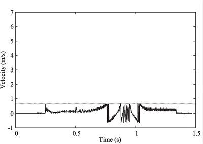
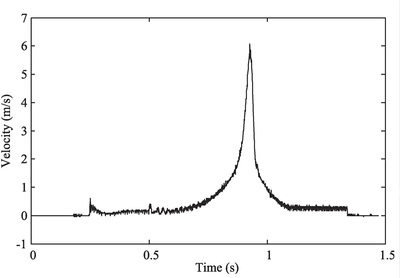
At the UVa EE department, work progressed on a prototype algorithm capable of tracking analog quadrature outputs with frequency contents higher than the Nyquist frequency. After several iterations, university researchers developed an algorithm that maintained a model of the current situation (position, velocity, acceleration) to allow future state prediction. In its simplest form, the algorithm replaces the original velocity constraint with an acceleration constraint. In many applications, this acceleration constraint might exceed any acceleration that the system could reasonably undergo. Using this technique, developers can determine without ambiguity the encoded rodís current position. The algorithm is, in fact, generalizable to higher degrees, replacing the acceleration constraint with higher-order derivative constraints. Figures 1 and 2 illustrate the improved results obtained with the new algorithm.
|
| (Click graphic to zoom by 2.0x)
|
|
| (Click graphic to zoom by 2.0x)
|
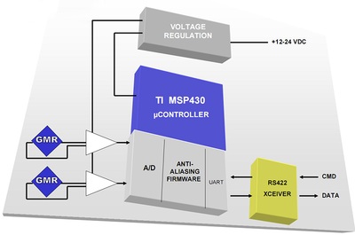
Developers selected the Texas Instruments MSP430 microcontroller as the host for the embedded firmware implementation of the anti-aliasing algorithm. The MSP430 includes numerous A/D channels, timers, flash memory, low-power operation, and a simple programming interface. The firmware was developed in the C language for the MSP430 using the CrossStudio (Rowley Associates Ltd.) The flash memory on the MSP430 retains the firmware and allows for field upgradability if new versions of the firmware need to be delivered to the sensor.
Circuit design and packaging
To complete the design, the GMR outputs were fed into an amplification circuit that minimized the effects of common mode, bringing the voltage into a convenient range for the MSP430ís A/D module. The circuit also included two embedded voltage regulators, one for the digital components and a separate 5 VDC regulator for the analog portions, including the GMR components. For communicating data and commands with the host computer, an RS-422 transceiver based on the Intersil ISL83488 was built into the circuit.
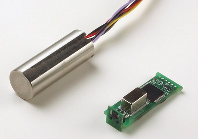
Figure 3 shows an overview of the system architecture. In its final form, the circuit is laid out on both sides of a 14 mm x 40 mm PCB. The board includes an area for a flux-inducing rare earth magnet, as illustrated in Figure 4.
|
| (Click graphic to zoom by 2.0x)
|
|
| (Click graphic to zoom by 2.2x)
|
Final thoughts: University partnership
When R&D departments need external help developing a new product or prototype, they typically turn to consultants or contract R&D organizations. It is less common to consider looking to universities for assistance.
However, when R&D includes cutting-edge software algorithms or technologies, a well-run university research lab can deliver important advantages. One is business competitiveness: The technologies that result from the work are more likely to be completely novel and therefore readily protectable (via patent or simple trade secrecy). In contrast, a contract R&D organization has a strong interest in reusing techniques they relied on in the past.
Another advantage of funding university research is that it can be less expensive. Universities typically do not charge by time and materials, but instead via a fixed price contract. Universities have noncommercial means to support overhead and infrastructure, and research contracts do not have to support these costs to the extent they would with a commercial partner. The personnel working on the project typically includes at least Masterís degree candidates and often PhD candidates in the field of interest, all of whom can bring considerable insight and energy to the table.
Sean Graves is VP of engineering and operations at Visi-Trak Sensors, based in Charlottesville, Virginia. Previously, he held management positions at firms including National Labtools, TekCel, and Biophile. He holds a BS in Computer Science from Angelo State University and MS and PhD degrees in Computer Science from Texas A&M University.
Visi-Trak Sensors, LLC
216-524-2363
sgraves@visi-traksensors.com
www.visi-traksensors.com